|
|
A Model Railroad Manufacturing Co. |
 MNP QR Code

![]()
![]()
|
|
| Outline1. The Smoke Kit for Engines (HO)2. The Pump Kit (All Sclaes)3. The Smoke Kit for Structures (All Scales)KIT Instructions: (Please Copy for your records)
THE SMOKE KIT
PARTS LIST For All, HO
Scale Engines.
2. Split Ring (To hold Seuthe Element to Metal Stack)
3. Metal Smoke Stack (negative electrical connection -)
4. Insulator (Insulate between Positive and Negative charges)
5. Contact spring (Contact for bottom of Seuthe Element)
6. #24 gauge wire (positive Electrical connection +) 
Basic Instructions:ASSEMBLY
INSTRUCTIONS FOR YOUR "SMOKE Kit
for Engines" BACKGROUND
FACTS ABOUT YOUR "SMOKE KIT for
Engines" This kit will add to the realism of putting "Smoke in your stack right on the track" once installed into your Engine. This kit is very versatile and can be added to a chimneystack to produce smoke for a factory or other manufacturing plants with MNP's PUMP KIT. This kit contains all the necessary parts, which can be modified to fit into all types of Engines or structures. The kit is Primarily for HO Scale Engines but can be used for all scales in model railroading. Obviously, this is not a stand-alone kit. Once you decide to install this kit into your Engine or structure, please follow the instructions in READ THIS FIRST for the steps needed for installation. IMPORTANT
-- READ THIS ENTIRE PAGE FIRST !!! 1. Before beginning to assemble your Smoke kit read all the instructions, tips through once, and familiarizes yourself with all the parts and their proper location by comparing them to the drawings. All parts are numbered to corresponding picture on the Back. 2. Decide the structure or Engine in which to install the Smoke kit and the EXACT location of the ENGINE or structure. Once the Smoke kit is installed, it is very difficult to move or install into another Engine. If you are a HO scale model railroader, sample instructions will be illustrated in the assembly instructions, but if not the instructions can still be applied to any application so do not worry. 3.
SEE THE BACK OF THE COVER PAGE FOR THE PARTS LAYOUT! ____________________________________________________________________________________________________________ TIPS: Smoke Stack: 1. Measure the OUTSIDE Diameter (0.2490" or 1/4" Dia.) of the Metal smokestack. When Drilling a Hole make sure that the Metal is a tight fit. This will be the (negative -) ground for the Smoke element. 2. Remove all the Burrs on the Metal smokestack. 3. Measure the total Length of the metal smoke Stack (1.16") Spring/wire: 1. Solder the Wire (RED, positive) to one end of the spring. 2. Make sure the spring fits into the insulator. (IT MUST NOT TOUCH THE OUTSIDE OF THE INSULATOR) and the wire travels through the insulator. 3. On the otherside of the Spring Bend the TOP COIL only to close the gap, to ensure Better Contact with the bottom of the Seuthe Element. Insulator
Check: 1. File or trim the OUSIDE of the insulator so that it is a very tight fit into the smokestack. DONOT PUSH the Insulator into the smokestack at this time. 2. The insulator must be tight so that it will not move when installed into the smokestack. Slip
Ring: 1. Place the Slip Ring onto the Seuthe Smoke Element. 2. Gently place it into the smokestack. 3. FROM THE BOTTOM Side of the smokestack, measure the distance to the bottom to the Seuthe Smoke Element. 4. This is where the spring and the Insulator must be to make contact to the Bottom of the Seuthe Element. Insulator
Installation: 1. Once you determine the exact position of the insulator, push it into the smokestack. 2. Now, install the spring and wire into the insulator. 3. Gently push the Slip Ring and Seuthe Element into the smokestack. (PLEASE TEST USING THE RED AS POSITIVE +, AND THE OUTSIDE OF THE SMOKE STACK AS NEGATIVE -) (PLACE A FEW DROPS ONTO THE ELEMET, SO IT WILL NOT BURN OUT!!!) CAUTION:
THE ELEMENT WILL GET VERY HOT!!!!!!!! Once you have tested the Smoke Element, you are NOW READY to install it into your Engine. Unfortunately, we at MNP Do NOT have all instructions for all Engines. This will be up to you! However, Feel Free to CALL US! General
Tips: 1. The Metal Stack Must be grounded (Negative -) Always. The Stack must fit tight into the Hole you Drill. 2. Run the wire (Red, + Positive) to the positive lead in your Engine or Structure. 3. Plan each step Carefully, take your TIME! CALL
for Technical Assistance or spare parts, We will be glad to HELP
à
à
1-757-596-2309 Thank you for purchasing this fine kit, and look for other kits soon!!!!
ASSEMBLY
INSTRUCTIONS FOR YOUR "LIQUID
SMOKE, PUMP KIT" BACKGROUND
FACTS ABOUT YOUR "LIQUID SMOKE,
PUMP KIT" This kit will add to the realism of putting "Smoke in your stack right on the track" once installed into a water tower, or water pipe, on your layout. This kit is very versatile and can also be added to a chimney stack to produce smoke for a factory or other manufacturing plants with MNP's SMOKE KIT. This kit contains all the necessary parts which can be modified to fit into all types of structures. The kit is for all scales in model railroading. Obviously, this is not a stand alone kit. Once you decide to install this kit into a structure, please follow the instructions in READ THIS FIRST for the steps needed for installation. IMPORTANT
-- READ THIS FIRST 1. Before beginning to assemble your pump kit read all the instructions and tips through once and familiarize yourself with all the parts and their proper location by comparing them to the drawings. All parts are numbered to corresponding picture on page 2. 2. Decide the structure in which to install the pump kit and the location of the structure on your railroad layout. Once the pump kit is installed it is very difficult to move or install into another structure. If you are a HO scale model railroader, sample instructions will be illustrated in the assembly instructions, but if not the instructions can still be applied to any application so don't worry. 3. Decide the location of your reservoir, be sure to install it in a location easy accessible for refilling and the shortest distance to the pump as possible. This will reduce the amount of liquid smoke needed for maintaining the pump system. 4. Decide the location of the push button which you can easily see the smoke stack of your engine and the end of the hollow metal tube to enable you to see the actual action if installing it into a water tower which is widely used. 5. Once you decide the location of the main components, it will be very easy to complete the installation of this kit, so plan ahead. 6. The electrical pump uses 6 volts only. The kit is equipped with a battery holder for (4) C batteries which can be mounted anywhere on the layout. An A/C and or DC converter can be used to reduce the voltage from 12 Volts DC to 6 Volts DC if you do not want to use the battery holder. TIPS 1. The most important installation is the hollow metal tube. Once the decision is made to fit and bend the metal tube, it is very difficult to readjust the tube. SO BE CAREFUL!!!! Once installed, the end of the tube should be slightly higher than any point along the tube. This will prevent dripping out of the end of the tube. 2. Once the pump, reservoir, battery holder, and structures are mounted, the hoses can be easily run at the correct length. Use the connectors as an intersection point when adjoining the hoses from the reservoir and tube to the pump hoses. 3. When installing the suction hose in the reservoir the end of the hose should be slightly higher than the bottom of the reservoir. Cut the bottom of the hose on a slight angle so it can always pick up liquid smoke. 4. Once the pump, push button and battery holder are mounted the electrical wires can be easily run at the correct length. 5.
When installation is complete and all hoses are connected, priming the system is
necessary to remove all air from the hoses and pump. When priming the pump
system fill the reservoir full of liquid smoke, push the button using small
intervals to allow the oil to slowly move through the system. Do
Not continuously run the pump!!! Note:
It may take 5 minutes or so depending on the length of the hoses to
completely prime the pump system. Once the system is primed, there should be no air in the hoses and
the liquid smoke should drip out of the tube with no bubbles.
A
Completed system installed into a water tower used in HO scale.
The description and assembly for this pump system are
located on the following pages. The basic assembly and operation will be
discussed on the following page. Remember
it is up to you to decide what application this pump kit will be modified to fit
into. The parts are numbered by the following: Part
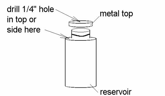
no. 1. The optional battery holder will hold 4 C batteries for independent operation, or a converter can be used to hook up to your system. CAUTION the electrical motor can only hold 6V!!!! 2a,2b,2c. Are the electrical wires. The wires can be run according to the diagram. 3. The normally open electrical push button which will activate the circuit can be wired according to the diagram. The push button should be mounted in a line of sight to the hollow metal tube, so that when pushing the button you can see the liquid smoke drip from the tube into the engine's smoke stack. 4. The reservoir which will store the liquid smoke. The reservoir should be mounted in a place for easy access so refilling of liquid smoke is easy. A 1/4 hole in the metal top must be made so that the suction tube can be installed. The suction tube can be modified for any suitable position on the plastic reservoir. The option is yours.(see following diagram) IF you want to install the hose at the bottom of the reservoir you will need to call MNP for extra fittings. 5a,5b. Is the suction side of the pump with the large O.D. plastic tube. The plastic tubes should be hooked up last to ensure the correct length. DO NOT cut the hose short.
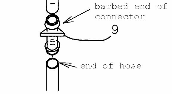
6.
The large connector will adjoin the hose from the pump and hose from
the reservoir. Make sure that the both barbed ends of the connector are
completely covered by the end of the plastic hoses. This
will ensure no leakage of liquid smoke. 7. Is the electrical piston pump. The pump should be mounted in the away that the shortest distances can be run by the hoses. Located on the pump is a 90 fitting, this is the pressure side of the pump. (See picture) Also, the pressure side has the small inside diameter hose. The suction side is located with a straight fitting and with the larger inside diameter. The pump can be wired in either positive or negative direction when the wires are installed 8a,8b. The pressure hoses of the pump with are the small I.D. plastic tube. The plastic tube should be hooked up to the hollow metal tube before adjoining it the connector. 9. The small connector will adjoin the hose from the pump from the hollow metal tube. The plastic tube at this end should be hooked up last to ensure the proper length. 10. This is the MOST IMPORTANT part in your pump assembly!!!!! When bending the hollow metal tube take the following precautions: a) Install a wire inside the hollow metal tube before bending at each end only, this will ensure that the tube will not have a sharp pinch point at each critical bend. b) Decide the exact modification that the tube needs to be modified for your application. c) As shown below the critical bending points must be done very carefully, so that the tube will not be damaged.
11. As shown on page two, the pump system is installed into a water tower, note that the hollow metal tube is installed into the spout of the existing water tower. The hollow metal tube can be used to fit other applications. Other
key points: When installing the hoses on the barbed connectors (9), make sure that BOTH ends of the hoses are over the barbed end for a secure tight fit, which will ensure a leak proof system. When installing the hose over the hollow metal tube this is only a friction fit the hose will only be approximately 1/8" on the metal tube. (See diagram below)
When installing the suction hose in the reservoir, you can either drill a 1/4" hole in the metal top or the top part of the plastic reservoir . It is your option depending on the location of the reservoir. The main concern is to have the suction hose located to pick Up the liquid fluid. (see diagram below). IF YOU NEED EXTRA FITTINGS or HOSES, PLEASE CALL: 1-757-596-2309
You
can ORDER EXTRA HOSES AND FITTINGS for other USES CALL 1-757-596-2309. Thank
you for purchasing this fine kit, and look for other kits soon!!!!
"THE SMOKE KIT for Structures"
ASSEMBLY INSTRUCTIONS FOR THE SMOKE KIT BACKGROUND
FACTS ABOUT OUR "SMOKE
KIT" This kit will add to the realism of putting "Smoke in your stack right on the track" once installed into ANY STRUCTURE on your layout. This kit is very versatile, shown below the Smoke Kit and (Pump kit if used together) are added to a chimney stack to produce smoke for a factory or other manufacturing plants.
This kit contains all the necessary parts which can be modified to fit into all of structures. This kit is for all scales in model railroading. Obviously, this is not a stand alone kit. Once you decide to install this kit into a structure, you will enjoy the ease of operating the pump kit to install liquid smoke into your structures as shown in the picture. 1. Decide the structure in which to install the smoke kit and the location of the structure on your railroad layout. If you are a model railroader, a sample illustration is shown below, but if not, the instructions can still be applied to any application, so don't worry. USE ONLY 12 VOLTS max.FOR WIRING THE SMOKE ELEMENT. A DETAILED VIEW of The Smoke Kit and Pump Kit installed into a CHIMNEY STACK, WHEN USED TOGETHER! THIS IS THE BEST AUTOMATIC SYSTEM FOR PRODUCING SMOKE!
2. When installing the smoke element into any structure, the following precautions must be taken: a. All bare wires must NOT make contact with any of the plastic structures. b. The probe on the smoke element must be exposed to the outside at the top of any stack, DO NOT cover the smoke element. c. Always INSTALL the Insulator around the inside of any structure. 3. Recommended to use MNP Design's Liquid Smoke . When using the toggle switch, the smoke element must have liquid smoke at all times to prevent burn-out!! CAUTION: WHEN NOT IN USE TURN OFF ALL ELECTRIC POWER TO THE SMOKE ELEMENT. 4. To operate the smoke element, switch the toggle switch ON to generate the smoke, for hours of enjoyment. MNP IS NOT RESPONSILBE FOR ANY DAMAGES! |
Send mail to [email protected] with
questions or comments about this web site.
|