|
|
A Model Railroad Manufacturing Co. |
 MNP QR Code

![]()
![]()
|
|
|
DCC Decoder Installation Instructions for the N-Scale Motorized Track Cleaning Car
THANKS for purchasing our custom DCC Decoder for you NEW
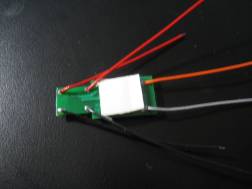
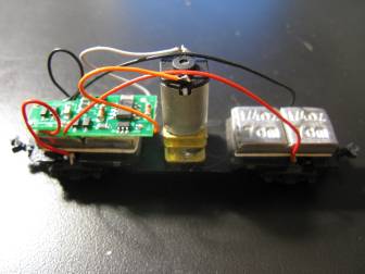
N-Scale Motorized Track Cleaning Car! For Questions & Technical Help Please Call or write to: MNP Inc. Pictures for N-Scale DCC Motorized Track Cleaning Car
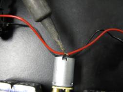
#1, (Foam Tape) Note Position & Size #2, Un-solder motor leads
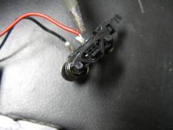
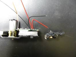
#3, Un-solder Truck leads #4 Bend Wire leads for motor & trucks
#5 Final Installation of the Decoder
TECHNICAL INFO BELOW: Fine
tuning for N-Scale Track Cleaning Car operation : The
factory settings normally provide good performance
for most locomotives in HO-Scale. You
may want to improve or fine tune performance by adjust the starting
characteristics or top speed . There are 2 CVs that define: Ù
The
maximum motor speed Ù
The mid
speed range response characteristics or ‘speed curve’. Vmax - CV5: If your locomotive runs too fast you can use CV5 to lower its maximum
speed. Setting CV5 to 255
uses the maximum possible voltage to run the motor when full speed is requested.
Set CV5 to a smaller value to reduce the top speed.
A value of 128 will yield approximately ½ full voltage to the motor at
top speed. 192 will provide about
¾ full voltage. All speeds
from the middle speed step to the maximum will be proportionally reduced (see
diagram). If CV5 is set to 0 the
decoder will use 255 for maximum speed. Always
make sure CV5 is greater than CV6 to avoid erratic operation. Vmid - CV6: CV6 determines how the motor responds through its middle speed ranges
to advancement of the throttle. If
you set CV6 lower than half the maximum speed you’ll have smaller increases in
motor speed through the lower speed ranges.
Then, as you hit the upper speed ranges there will be larger increases
between speed steps. In the
diagram below you can see this best illustrated by the factory default line.
If you set Vstart larger than 0 you’ll will most likely want to raise
Vmid so a reasonable slope is maintained in the ‘speed curve’.
If CV6 is set to 0 the decoder will use 127 as the value.
If you use high values in CV57 you will want to increase CV6 by a
proportional amount to keep a smooth acceleration curve. Reverse trim (also forward trim) - CV95: Values
from 1-127 make decoder run faster in
reverse than forward. 1 is one
speed step faster in reverse, 2 is two steps faster, etc. Values
from 129-255 make decoder run faster in
forward than reverse. 129 is one speed step faster in forward, 130 is 2
speed steps faster, etc. 0 and 128
add nothing to either direction.
Factory default values for decoder Configuration Variables (CVs)
Configuration Variables used by V3.5 Decoders CV1 Short decoder address; 1-127 valid CV2
Start
Voltage (useful range 0-100) CV3
Acceleration
rate (each unit
= 7mS
between speed steps)
255 max.
CV4
Deceleration
rate (each unit =
7mS between speed steps)
255 max. CV5
Vmax, speed at highest speed step.
0=use factory default of 255 CV6
Vmid, speed (on a scale of 1-255) at speed step 7,14,or 63.
0=use default of 127 CV7
Decoder
version number.
This decoder is 35 which means version 3.5 CV8
Manufactuer
ID. = 11 (0B hex) CV17
High byte of long (4 digit) address - bit 6,7 always= 1
- bits 0-5
are upper 6 bits of address CV18
Low
byte of long (4 digit) address CV19
Consist
address. (0 or 128 = no consist active)
- bits 0-6
short consist address (1-127 valid)
- bit 7
0= direction is normal, 1= direction is reversed CV29
- bit 0
1= direction of operation is reversed, 0= direction is normal
- bit 1
1=28 speed mode (always enabled)
- bit 2
1= analog operation mode enabled, 0 = disabled
- bit 4
1= alternate speed table active, 0= use table defined by CV2,5,6
- bit 5
1= use long address in CV17/18,
0= use short address CV1
- bits 3,6,7 are ignored by the decoder CV30
Set
this CV to 2 on the programming track
and the decoder will reset to factory settings. CV67-CV94 Uploadable speed table steps 1-28 (128 speed mode calculates
intermediate steps) CV NOTES: All CV numbers not listed above are ignored.
This decoder supports all DCC programming methods.
| ||||||||||||||||||||||||||||||||||||||||||||||||||||||||||||||||||||||||||||||||||||||||||||||||||||||||||||||||||||||||||||||||||||||||||||||||||||||||||||||||||||||||||||||||||||||||||||||||
Send mail to [email protected] with
questions or comments about this web site.
|